 Articles
How To Better Identify A Cold Solder Joint
by Howie Liu Electronics EngineerAbstract
Soldering is the most basic skill required to assemble any electronic circuit. Soldering is a chemical process in which solder (a mixture of tin and lead) is heated to flow over the two joined surfaces: i.e., the PCB and the component pin. Cold Solder Joint takes some practice and theoretical background to make a perfect joint and with speed. The soldering compound is hard and elastic at room temperatures but it melts rapidly beyond 160°C temperature. The soldering iron or soldering station is the tool that heats the solder to flow.
A soldering iron is generally a single tip of hot metallic needle fixed in the heating element and is not a temperature controlled tool. The soldering station, although is costly, is a temperature controlled tool that maintains the temperature of soldering tip within limits of defined temperature settings. More the temperature is controlled and maintained and the perfect solder compound the more perfect is the soldering joint.
Content
1.What is a solder joint
2.Identify cold solder joint
3.The use of solder joint
1.What is a solder joint
The ideal soldering joint is like a concave fillet. The solder starts from the base on the component on the PCB, flows upwards to the pin height like a capillary action and inside the hole of the pad. A good soldering joint should look like as shown in fig 1.
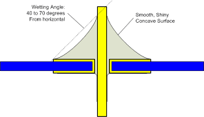
Fig. 1:- Drawing of an ideal PCB soldering joint
2.Identify cold solder joint
A bad or cold solder joint is where the solder does not melt or flow completely. It is often identified by the rough and unsmooth surface. Their major drawback is they are unreliable and becomes cracked and broken over the time. In fig. 2 different possibilities of soldering joints are shown for the through hole components pads.
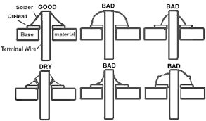
Fig. 2:- Different schemes of soldering
3.The use of solder joint
The colder joints, if needed, require re-work although not very much for the joint! They are repaired by just re-heating the joint and flowing the solder properly. However, for a product, it takes much time to unassemble and reassemble it. It causes product failure, technicians' maintenance time, customer dissatisfaction and plant or machine downtime. An ideal and cold solder joint made on a single component is depicted in the fig. 3 below. In figure 4 different defects of cold solder joints are shown that appeared over the time in a product.
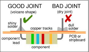
Fig 3:- Ideal and cold soldering joint on a component
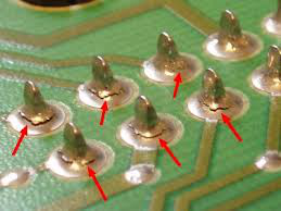
Fig 4:- Problems due to cold solder joint that may appears over the time
Conclusion
A cold solder joint can be avoided by using properly pre-heated soldering iron with enough time and power. Another problem that occurs, similar to the cold solder joint in physical inspection, is due to overheated soldering irons. They can be repaired by cleaning and re-flowing the solder over the joint. The practices and problems which are discussed for through hole components. They are equally applicable with small exceptions to the SMD components.
Sponsor Ads
Created on May 10th 2018 01:34. Viewed 380 times.

