PCB vs PCBA-What is the Differences(Better Compare)
Abstract
To be able to discuss PCB vs PCBA, it is important that we look at what PCBs and PCBA are. Printed circuit board refers to a surface that connects electronic components using pads, conductive traces, and nonconductive substrates. It can either be single or double sided.While PCBA refers to a board that has components and parts soldered & installed on the printed circuit board, and ready to be used in devices it is designed for.
Content
1.Introduction
2.History of PCBs
3.PCB vs PCBA-The Differences
4.Types of Printed Circuit Board
5.Conclusion
1.Introduction
The PCB could also have both the inner and the outer layer. Hundreds of conductors may be found on different layers and are all connected via holes. Pcb boards may have multi-layers meaning that they have a higher component density that allows them to be used in a wide range of applications.
2.History of PCBs
PCBs have a long history and have evolved from the simple systems developed in the 1850s when metal strips and rods were used to connect electric components, most of which were mounted on the wooden bases. Later metal strips were used and wires connected to the terminals. This increased the need and application of the boards. Charles Ducas submitted a patent for creating an electrical path on an insulated surface. Paul Eisler patented a method of etching circuits in 1943. It was widely used alongside transistors in the 1950s.
It helped to reduce the size of components that were used and gave birth to the modern PCBs. Transistors were then introduced in the 1950s, which greatly reduced the size of vacuum tubes in devices. Given the size of the components, it necessitated that traditional mounting and wiring methods be used. As the components became smaller, it forced the manufactures to resort to printed circuits to reduce the size of electronic devices. Hazeltyne, A U.S. firm patented the use of PCBs in 1961. This increased the component density and allowed for spacing of electrical paths which brought about a new era in PCB design.
Thus, the present PCBs boards which are designed to perform a specified function can be traced back to 1961. However, the PCBA which come with components mounted are relatively new and complement PCBs.
3.PCB vs PCBA-The Differences
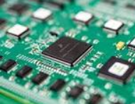
The printed circuit refers to a module of interconnected components found in devices that feed on the radar, common pages, radios and computer system. The circuits may be constructed using a thin layer of materials which are deposited or printed on an insulating board referred to as a substrate. The individual components are then placed on the substrate and soldered to the board using interconnecting circuits. PCBs have circuits that perform a wide range of function including amplification and much more.
PCBA on the other hand refers to a board that has mounted components. The board comes with components like capacitors and integrated circuits mounted. The board undergoes reflow heating which helps to establish a connection between the components and the PCB. PCBs utilizes contact fingers on the edge of substrates which act as connectors to external devices and other PCBs.
4.Types of Printed Circuit Board
To be able to understand PCB vs PCBA, it is important that we look at the types of PCBs. Here are the most common PCBs that you will find on the market.
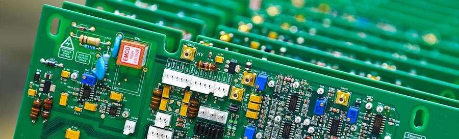
Single-sided PCBs- they have components on the side of the substrate and can accommodate a sizeable number of components.
Double-sided - When the components on the substrate become too many a double sided board needs to be used. Typically, holes will be drilled through the substrate which is then plated with a conducting material.
Multi-layer board,it consists of a substrate consisting of layers of circuits which are separated by an insulation layer. Components are electrically connected to circuits using the mounting technology. The components use leads, or thin wires to push through small holes. Friction and gravity between the holes and leads are kept in place by friction and gravity. To mount components, on multi-layered board, it is necessary to apply glue and flux on the components to hold them in place. This is what is referred to as mount technology, which is used to place components on the board, it eliminates the need for drilling holes into the board. Also, this technology allows one to use two or more boards in a circuit.
5.Conclusion
It is important to note that board designers use computer-aided design and software to lay out the circuits that will be used for a specific function. The computer helps to locate the spaces for electrical wiring as well as the holes. The information is then translated into executable instructions that could be implemented by a drilling machine. After laying out the circuit pattern, a mask is then printed on a plastic sheet.To know this two definitions better then you will know more about PCB VS PCBA.

Post Your Ad Here
Comments