PLCC32 Programmer ,the PLCC32 Flash Programmer OBD 2 Tool
 The PLCC32 Programmer is the obd 2 tool.If you have the Plcc 32 Programmer , how to use the PLCC32 Programmer?
the PLCC32 Flash Programmer you know is the good obd 2 auto scannner parts.
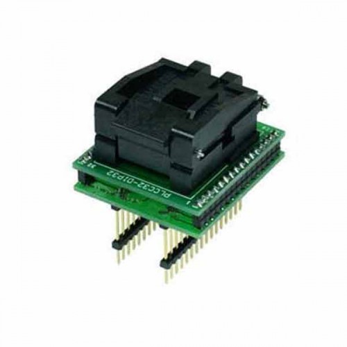
why to say so ? you can see the images of the PLCC32 Programmer:

This PLCC32 Programmer is the typical PLCC32, in vtoolshop china, I think this tool is good and the work of the PLCC32 they have done well.
Here is some technology parameter you can see:
ATF16V8, ATF20V8, ATF22V10
Atmel specifies that these PLD devices with FLASH memory technology have to be conditioned prior to initial programming. This means that the whole device is completely programmed twicewith 0, and erased again afterwards. Verifying errors can be ignored during conditioning. A JEDECfile suitable for conditioning is part of the software supplied with
hed.chip
. Example for ATF20V8:
hedchip /ga20v8 /p/e conditio.jed ; program oncehedchip /ga20v8 /p/e conditio.jed ; program twicehedchip /ga20v8 /e/v ; erase, blank check
So if you will find the PLCC32 Programmer you should have a look at the PLCC32 manual and know the details of the tool , it can help you to know the tool well.
The relative tool is PSOP44 Socket
PSOP44 Socket Adapter Manual
-Insert adapter to the device programmer ZIF socket according to the picture placed near of it. If you have
some doubts about orientation of this adapter in device programmer ZIF socket, it is valid general rule, the
orientation of the text of title is the same as the text on -the top of the device programmer.
-Push the top of adapter ZIF socket to open it. Insert the device into the adapter ZIF socket. The right position
of the programmed device in adapter ZIF socket is show at picture near (mainly left above) the adapter ZIF
socket. Then release adapter ZIF socket. If you use this adapter for devices with less than 44 pins, then place
device to the bottom edge of adapter ZIFsocket. Upper contacts stay unconnected.
-Visually check interconnection between device and adapter ZIF socket. If everything looks OK, the device is
ready for programming.
-Be careful, because the incorrect insertion of adapter to the device programmer ZIF socket or device to the
adapter ZIF socket can damage the programmed device.
-To take out the device push the top of adapter ZIF socket and remove device from it.
-When you finish work with adapter, remove it from the device programmer ZIF socket.
-Do not directly touch the pins of the adapter and adapter ZIF socket, because dirt may cause errors during
programming of device.
-For handling with the device we recommended to use a vacuum pick up tool.
-If programming yields isn't 100% when using programming adapter or if some unreliability appears, try to
connect one 22nF-100nF multilayer capacitor (that meet the EIA X7R or Z5U specification) between leads of
adapter connected to pins VCC and GND pins of programmed chip.
See more obd 2 tools go to see VtoolShop.
Advertise on APSense
This advertising space is available.
Post Your Ad Here
Post Your Ad Here
Comments