 Articles
PCB Assembly - How To Be More Professional
by Warren C. Electronics EngineerPrinted circuit boards are the driving force behind a wide range of electronics. You can find them in simple products like calculators and advanced military and satellite systems.
However, do you know how to assemble a PCB? Do you know the steps involved in the process?
There's no need to fret if you don't! We have created this in-depth guide on PCB assembly so that you get to know everything you need about the process. Then you can assemble your PCB and give life to your project.
In this guide, we will explore the process of PCB assembly and the different technologies used for the purpose.
1、 The Printed Circuit Boards Assembly
The printed circuit board assembly is the process of mounting or placing electronic components which give the board its functionality. The electronic components can be mounted by manual and automatic techniques, and then they are soldered in place.
It would help if you did not confuse it with printed circuit board (PCB) manufacturing which involves the production of the PCB and creating prototypes. Covers the installation of electronic components during the assembly process, and the board is called the PCBA or printed circuit board assembly.
Different technologies can be used to assemble a PCB which include SMT and THT processes. We will explore them in details in chapter 4 but for now, let's take a look at a PCB design.
2、Printed Circuit Design and Fab
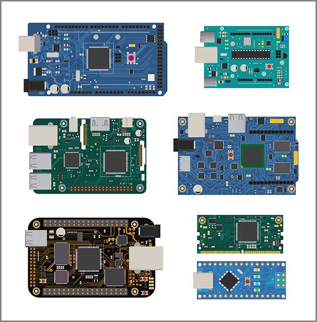
You can use a Computer Aided Design (CAD) solution to design PCBs using schematics. The design files or Gerber files are then handed over to the manufacturer who produces or assembles the PCB according to the design.
The basic design of PCBs include-
Substrate: The base material of a PCB is known as the substrate. It is what makes the board rigid and durable.
Copper: Each functional side of the PCB is applied with a thin conductive copper layer. The number of sides that will require a copper layer depends if the board is single sided or double sided.
Solder mask: The green colored substance on PCBs is due to the application of solder mask. It provides insulation to the copper traces so that they don't come in contact with conductive components.
Silkscreen: Use a white screen as the last layer of the PCB. It contains the labels of different components in the form of symbols and characters.
PCBs can also be of three types-
● Rigid PCB made of solid material such as fiberglass
● Flexible PCB made of bendable materials such as Kapton
● Metalcore PCB made of metalcore
In the next chapter, we will discover the printed circuit board assembly process.
3、Printed Circuit Boards Assembly Process
3.1 Tools Required
You will need a minimum number of tools if you plan to solder your PCB manually. The things to arrange include-
● Soldering iron or soldering station
● Solder flux
● Pliers
● Wire Cutters
● Screwdriver
● Volt/OHM meter
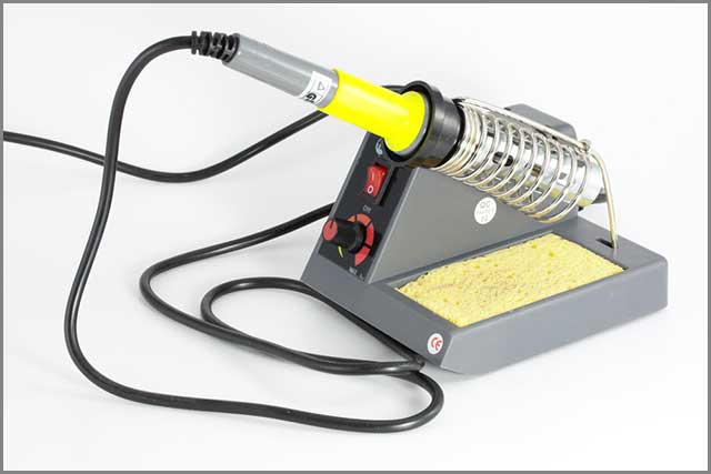
3.2 Soldering Equipment
You can choose from a wide range of soldering equipment for manual printed circuit board assembly. The most simple ones plug right to the power outlet and don't have any options of temperature control. You should select a 15 to 30-watt soldering iron for your PCB assembly.
The thermostatically controlled soldering irons can be suitable as they come with options to control the temperature. Some have dials to control the temperature while others use a magnetized tip with a specific temperature.
The tips begin to magnetize as you increase the current flow causing the temperature to rise. When magnetism comes down the heat also reduces. It would help if you chose a soldering iron with replaceable tips of different sizes.
You may also need a hot air soldering station which uses hot air to melt the solder.
3.3 Types of Solder
You will find different types of solder in the market and choose according to the purpose and application of your project. There are three types of solder used for electronics-
● Lead alloy solder
● Lead-free solder
● Silver alloy solder
Lead Alloy Solder
Lead alloy solders are made from a combination of lead and tin and may also contain traces of other metals. Lead is responsible for giving the solder a lower melting temperature which is significant as most electronics are heat sensitive.
Lead alloy solders are defined by the ratio of the weight of tin followed by the weight of lead. For example, it could have a ratio of 60:40 or 63:37- the first number represents the amount of tin while the second refers to the amount of lead.
You can use both solder types for common electronic applications. The 63:37 alloy can effectively transform into the liquid state and helps prevent cold solder joints.
Lead-based alloys are used as a standard in the electronics industry but can have health consequences.
Lead-Free Alloys
You may be able to come across lead-free alloys such as the 96.5:3:0.5 which has 96.5% tin, 3% silver, and 0.5% copper. Lead-free alloys are more expensive than lead-based alloys and have a higher melting temperature.
Lead-free alloys create stronger solder joints though they may be brittle.
Silver Alloy Solder
Silver alloy solders may or may not contain lead. Silver was first used in solders to create stronger and durable solder joints. Silver alloy solders tend to be more expensive that lead-based and lead-free alloys.
3.4 Proper Soldering Technique
You have to take help of soldering methods multiple times during printed circuit board assembly. It is crucial that you use proper soldering techniques to get the highest quality end products possible. Here we will tell you how you can use proper soldering techniques during the PCB assembly process.
The proper way to solder is to heat the surfaces that will solder beyond the melting point of the solder. It enables the solder to flow over the surfaces freely. It would help if you also kept a check on the amount of the solder making sure not to use too much.
You also have to ensure that the surface is heated enough to prevent cold solder joint. It happens when you use to little heat to the surface, and the solder is not able to move freely.
The rest of the soldering process is carried out automatically by machines. The reflow soldering uses a series of heaters and cold heaters to melt and solidify the solder and make it firm.
You should ensure that the temperatures are correctly set in the reflow soldering machine. It needs to heat up to 250 degree Celsius to be able to melt the solder.
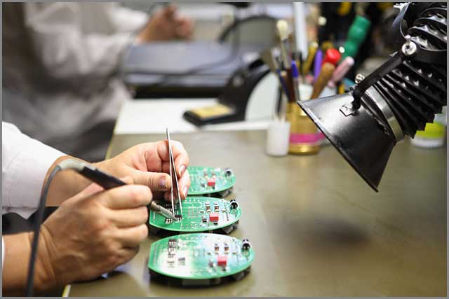
The manual soldering technique may be needed when you are dealing with THT components. You have to place the parts by hand and then solder the extra lead or wire on the other side of the board. It has to be done carefully so that the solder or flux do not touch the other components and only in the right place.
It would help if you also were careful not to inhale the fume or smoke coming from the flux in the solder. It may be difficult or challenging to solder PCBs if you are entirely new on the job. It would help if you practice first on some small projects and then try your hands on PCB soldering after you are a bit skilled.
Now we are going to check out the differences between the processes used to assemble PCBs.
4、 Differences in Printed Circuit Boards Assembly Process
You can use a different type of technologies to assemble the electronic components on a PCB. The main methods include Thru-Hole Technology (THT), Surface Mount Technology (SMT) and Mixed technology.
We will discuss the main differences and the process of PCB assembly for each method.
Through-Hole Technology (THT)
THT method of PCB assembly is used for electronic components that come with a wire or lead. The PCB comes with holes which are drilled into it to fit the components. The extra lead that goes through the holes is soldered on the opposite side of the board.
THT is used for large components such as coils and capacitors. It is also used for other plated through-hole or PTH parts which go through the plated through-hole of the PCB. Various PCB components use the holes on the board to transfer signals from one side to the other side of the PCB. For this reason, you cannot rely on soldering paste which will pass right through the holes.
Assembly Process
THT assembly makes use of both manual and automatic processes to place the components on the PCB. Proceed as follows -
1. Placing Components
Electrical engineers manually place the components on the PCB according to specifications. It has to be done quickly and accurately with full compliance to operation standards or regulations of THT assembly process for proper functioning.
For instance, it is essential to define the orientation and polarity of electronic components so that operating elements don't affect operating components.
2. Examining and Correction
You need to check if all the electronic components on the PCB have been placing accurately. It can be done automatically with the use of a transport frame. If you find any errors or mistake, the engineers can quickly rectify it.
3. Wave Soldering
These electronic components have to be soldered to the board in this step. You can do it manually, but a far more efficient and automated process called Wave soldering can be used.
The PCB placed on a conveyor belt which carries it inside a special oven which contains molten solder at high temperatures. The solder is applied on the bottom of the board which covers all the pins at once.
The electronic components are attached to the board with all lead or wire connections.
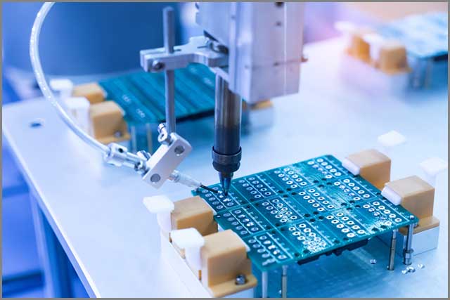
Surface Mount Technology (SMT)
SMT is the automatic process of placing or mounting electronic components on a PCB. SMT enables you to speed up the production process, but there are increased chances of defects. For this reason, the process also employs failure detection for creating functional products.
The electrical components mounted with SMT are smaller than PTH components and may or may not have leads. They sometimes come with pins, flat contacts or terminations on their body.
Assembly Process
1. Applying Solder
You have to use a solder paste printer to apply solder to the PCB. A solder screen or stencil is used to ensure the proper application of solder at valid points where electronic components will be placed.
It is crucial to have an efficient solder paste printing process as it directly impacts the quality of soldering. A solder inspector is used to find any defects in the quality of solder paste printing. If any errors are the spot, then the solder is washed off for a second printing.
For small defects, a rework can be sufficient.
2. Placing Components
A pick-and-place machine is used to mount the electronic components after solder printing. The machine automatically mounts the IC or components through component reels. They components reels are responsible for feeding the components to the machine which are then fixed onto the PCB.
3. Reflow Soldering
This step uses a specialized oven to harden the solder paste so that the components can be fixed firmly to the board. The PCB is carried inside a series of heaters which raise the temperature of the board to 250 degree Celsius. The high temperature melts the solder on the board
Next, the PCB moves through a series of cooler heaters which bring down the temperature and help the solder to harden. That adheres all the electronic components firmly to the PCB.
Mixed Technology
In the modern age, electronic products have increased in complexity requiring the use of different electronic components on PCBs. You will find the use of both THT and SMT technologies in a single PCB which contains both surface mounted and through-hole components.
Mixed technology is used in the following cases-
Single Side Mixed Assembly
In single side mixed assembly, the usual process of solder paste printing is carried out first. Then the surface mounted components are placed followed by reflow soldering.
Then you have to place the THT components and carry out wave soldering. You can also go for manual soldering if you are using a small number of THT components.
One Side THT and One Side SMT
First, you need to apply the surface mount adhesives and then proceed with mounting the SMT components. Then you have to place them in the oven for solidification followed by flipping.
Then you have to mount the THT components and perform wave soldering. This type of assembly process requires high cost because of the use of an increased amount of adhesives.
Double Side Mixed Assembly
It is a complicated and lengthy process where SMT components are placed after solder paste printing. Then you have to use adhesives for placing the SMT components on other side followed by solidification.
Next, the THT components are mounted ending with wave soldering. You can also carry out the process without the use of adhesives but need to use heating three times which results in decreased efficiency.
In the following chapter, we will find out how a PCB is tested to ensure its functionality and quality.
5、 Printed Circuit Board Assembly Testing
You will need to run various tests to determine the functionality of your PC assembly. It starts with the DFM check which involves checks the design specifications of a PCB for missing or problematic features.
The next test for functionality is carried out after the surface mounted components are placed and soldered. The board is tested for its connections and shorts which can occur if inappropriate connections have occurred.
Manually inspect the PCB after the reflow process. It can be useful for a small batch of PCBs but is not feasible for large-scale production. An automatic optical inspection machine is also used to test the PCBs using advanced cameras.
The machine can detect low quality solder by analyzing the way they reflect light.
One of the less conventional methods used for highly complex or multi-layered PCB involves X-ray inspection. The X-ray provides visuals of all the layers and can help find problems which are hidden from plain eyesight.
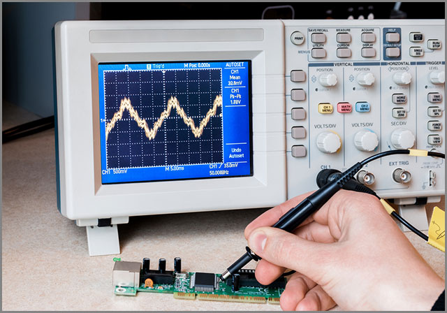
A final inspection and functionality test are carried out after the assembly process is over. You can determine the electrical characteristics of the PCB through simulated signals. Through the test, you can find out different aspects such as signal output, current, and voltage.
6、Conclusion
PCB assembly can be a complicated process or simple one depending on the number of electronic components you are using and their types. The best way to assemble a PCB is to specialize in maintaining all specifications and standards.
You can get in touch with us for printed circuit board assembly and high-quality end products that easily pass the function tests. We will ensure that the PCBs are assembled as per your design and instructions to deliver the best results.
Sponsor Ads
Created on Apr 4th 2019 04:10. Viewed 371 times.

