 Articles
How to Use Resistors in a Transistor Circuit?
by Hugh S. Electronic PartsIntroduction
As a passive two-terminal electrical device, in electronic circuits, Resistors are used to reduce current flow, adjust signal levels, to divide voltages, bias active elements, and terminate transmission lines, among other uses. Here are descriptions of resistor functions in transistor circuits.
1 Functions of Resistor
In short, the functions of resistor are to limit current, divide current, divide voltage, and convert electric energy into internal energy (heating) in the circuit. According to Ohm's law, through calculations, resistors in parallel and series connections can be used to achieve the desired current and voltage. Also there are different resistors and switches combined to produce voice-activated switches, photosensitive switches, infrared switches and so on.
1) Limit Current
In order to prevent the components connected in series from being burnt out by the excessive current and to ensure the normal operation of the electrical appliances, a variable resistor can usually be connected in series in the circuit.
2) Current Diversion
The resistor is connected in parallel to the component or circuit that needs to be shunted, and the voltage does not change. The function of this resistor is to divide current.
3) Voltage Diversion
Generally, electrical appliances are marked with a rated voltage value. If the power supply is higher than it, the electrical appliance cannot be directly connected to the power supply for a normal operation. In this case, a resistor with suitable resistance can be connected in series in the circuit to share a part of the voltage, therefore the electrical appliance can work at the rated voltage. At this time, the role of the resistor is to divide the voltage.
4) Provide Bias Voltage
In the transistor circuit, the resistor is connected between the base of it and the working voltage. At this time, the power supply provides a bias voltage to the base through the resistor, and the resistance can determine the bias voltage. The role of the resistor in the circuit at this time is to provide a bias voltage.
5) Negative Feedback
Used in the resistance between the base and collector of the transistor, then the feedback branch of the negative feedback circuit is formed in the circuit. At this time, the resistor plays a negative feedback role in the circuit.
6) Oscillation
Resistor and capacitor form an RC circuit, which can be combined in parallel and in series.
7) Damping effect
Connecting a resistor in parallel in the LC resonant circuit can reduce the Q value, at this time, resistor plays a damping effect.
8) Decoupling
The use of resistors in multi-stage amplifier circuits can prevent harmful low-frequency interference, which play a decoupling effect.
9) Convert Electrical Energy into Internal Energy (Heating)
When the current passes through the resistor, it will convert all (or part) of the electrical energy into internal energy, which will generate heat. This principle is often used in electric stoves and heaters in our lives.
10) Convert Current into Voltage
When current flows through the resistor, a voltage will be generated across the resistor. As shown in the figure below, the collector load resistor R2 plays this role, converting the current flowing through the resistor R2 into a voltage and outputting it from U0.
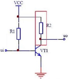
Fig 1. Resistor Circuit
2 Three Basic Principles for Resistor Selection
1) Choose resistors that are manufactured by a certification body that implement high-level standards.
2) Choose resistors produced by manufacturers with functional advantages, quality advantages, efficiency advantages, price advantages, and service advantages.
3) Choose a manufacturer that can meet the above-mentioned requirements in the model catalog.
3 The Role of Resistors in Transistor Circuits
3.1 Why should a resistor be added to the base of the transistor?
First of all, we must understand the basic principle of the transistor. It is a current-controlled element, which is different from the MOFET, a voltage-controlled element. The transistor has three working areas: cut-off area, amplification area and saturation area. Take NPN transistor as an example, the voltage difference(UBE)of BE is about 0.6V (the actual size depends on the model of the component). When UBE<0.6V , the transistor is off; when UBE=0.6V, the transistor is in the amplification or saturation region.
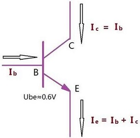
Fig 2. Schematic Diagram of the NPN Transistor Current
When the transistor is in the amplification area, the added resistance between the base and VCC is a bias resistance. The following explains why the base should be added when the transistor is used as a switch. What is the difference between transistor and MOSFET circuits when adding a resistor.
The following figure is the most commonly used circuit diagram of NPN transistors. The common input terminal is the I/O port of the microprocessor (microcontroller, DSP, ARM, etc.).
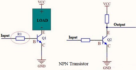
Fig 3. NPN Transistor
Take the microcontroller I/O port with 0/5V input as an example. Why must a resistor be connected in series with the base? Can it work without a resistor? Here the resistor is a current control element. When the transistor is in an amplified or saturated state, the voltage of the UBE is 0.6V, and the base current can be calculated according to the input voltage U. The calculation formula is Ib=(U-0.6 )/R1. It can also be seen from the formula that if the current limiting resistor R1 is not connected, when the input voltage is greater than 0.6V, the base current will be very large to burn the tube.
Moreover, the resistor cannot be used casually. It needs to be calculated according to the input voltage and the characteristics of the tube. For example, the amplification factor β of the transistor is 50, the maximum current of the collector is 500mA, and the input voltage is 5V. If the design requires the transistor to be in a saturated state, then Ic=500mA, Ib=Ic/β=10M=mA, where the current-limiting resistance R1=(5V-0.6V)/Ib=430Ω. If it is required to input 5V, the collector current is about 200mA, then Ib=Ic/β=200mA/50=4mA can be calculated, finally the current-limiting resistance R1=(5V-0.6V)/Ib=1075Ω (1K can be selected Standard resistance). Note: The above figure is used to explain the example, but it is not very reliable. A more reliable connection method should be to connect a large resistor (such as 10K, or 20K) between the base and the ground. When there is no input, pull the base down quickly to ensure that the tube is in a stable cut-off state.
If the NPN transistor in the figure above is replaced with an N-channel MOS tube, the principle is the same. When a high level is input, the tube is turned on, and when a low level is input, the tube is turned off.
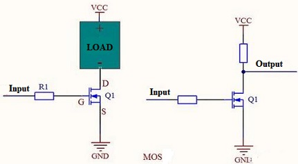
Fig 4. MOS Circuit
Since the MOSFET is a voltage-controlled device, the current of the gate (G) is very small and can be ignored, so it can work normally without connecting the resistor R1.
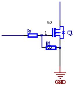
The figure after remove the resistor is shown in the below:
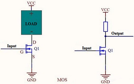
Fig 5. MOSFET Circuit without Resistor
Note: In actual applications, a resistor is generally connected in series to improve reliability. The product reliability is very important. Without current-limiting resistor, when the MOS is damaged by voltage breakdown, the components on the control terminal will be affected easily, especially the processor, is easily damaged by high current.
3.2 Pull-down Resistor in Transistor Circuits
For Transistors
The transistor is a current-type driving component, so a current-limiting resistor is connected to the base, generally less than 10K, and the typical values are 3.3K, 4.7K, 5.1K, 6.8K, etc. What is the function of this pull-down resistor?
The following figure shows the transistor 8050 switching circuit. The transistor will be turned on when the I/O port outputs a high level, and the transistor will not be turned on. If the I/O port does not output a high level, the base will always be pulled low without a 68K pull-down resistor, that is to say it is in the cut-off state. The circuit may be in an unstable state, especially when it is initialized at the moment of power-on. It is easy to generate noise and easily cause the transistor to malfunction, especially for some general input/output ports. Therefore, this resistor is actually a bias resistor, which makes the base to be pulled down when there is no driving signal, making the circuit more reliable.
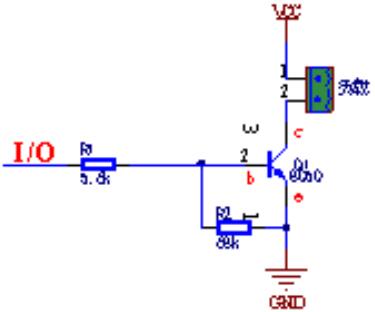
Fig 6. Pull-down Resistor in Transistor Circuit
Although the pull-down resistor can make the circuit more reliable, tit cannot be too large or too small. If the resistance too large, the base current will not be enough to drive the transistor. On the contrary, if it is too small, the bias voltage will be less than the transistor conduction voltage. In general, this resistance is not more than 100K.
Sometimes we see that a capacitor is connected in parallel with this resistor. In fact, this is generally designed in high-speed signal switching circuits. Adding a capacitor can improve performance, as shown below:
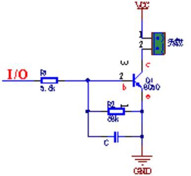
Fig 7. RC Circuit
For MOSFET
Unlike transistors, MOS transistors are voltage-controlled components, which are driven by voltage. We all know that there is parasitic capacitance between the two pins of MOS transistors. In fact, the key of MOS transistors’ conduction is the charging and discharging of capacitors. Therefore, for the N-type MOS, it will be turned on when Vgs is greater than a certain value, but for the P-type MOS, it will be turned on when the value of Vgs is less than a certain value.
Therefore, due to the capacitive effect between the three pins, when the MOS is constantly turned off, the parasitic capacitance voltage can be properly discharged, which is similar to the role of a bleeder resistor and is a kind of protection for the MOS.
Sponsor Ads
Created on Sep 25th 2021 02:36. Viewed 337 times.

Comments
No comment, be the first to comment.
