Cummins Genset Parameter Programming by Cummins InPower
This section describes how to make genset parameter value adjustments for trims and settings. There are a large number of adjustable trims and settings available for gensets. Not all genset models will have the same adjustments available. This section will cover typical adjustment examples, to help demonstrate basic procedures for using the adjustment features.
Note:Improper adjustment can cause equipment malfunction or damage. Adjustments must be
performed by trained and experienced personnel only. Refer to the equipment's Installation and
Service manuals for adjustment sequences and procedures.
Preparations:
Cummins InPrower Pro V12.5 V11.0 Free Download
How to Install & Activate Cummins Inpower Pro V12.5 and V11.5
Adjustment Basics
To access a group of adjustments or an individual adjustment, use Device Explorer to navigate the left pane until you reach the desired folder, and click on it. The right pane will display the parameter(s) associated with the adjustments for that feature.
Below shows a list of parameters for the Governor - Frequency selection.

The right pane displays the Parameter description, Value, Units of measure and the Last Time that the value was Read.
Placing the mouse pointer over a parameter will bring up an information popup box. The popup provides a brief description of how the parameter value is used.
NOTICE:
Some values may require that the genset is running or stopped before they can be edited. Refer
to the parameter's information pop-up for details.
Adjustment Features
The groups and the contents of the Adjustment features can vary by genset model, control software version, and InPower version.
The Adjustments directory for a typical genset contains the following groups (folders) of Adjustment options:
AC Measurement Calibration:This group contains Current, Voltage and Power Factor measurement parameters for the graphical display. Also contained in this group is the calibration for Voltage Measurement for Regulation.
Alternator Protection:Contains adjustments for Over and Under Frequency, High and Low AC Voltage, and related time delay settings.
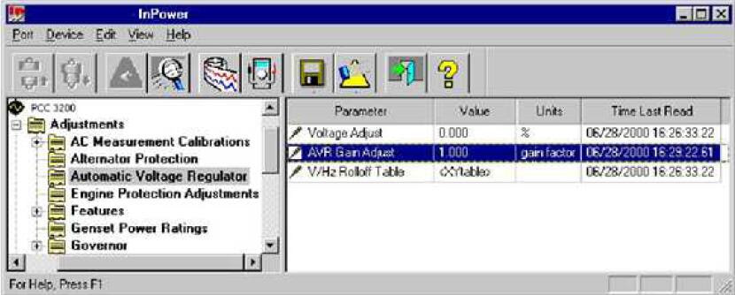
Automatic Voltage Regulator: Contains adjustments for the Voltage Adjust trim for the nominal voltage offset, overall AVR gain adjust, and the V/Hz rolloff table.
Engine Protection Adjustments:Engine protection settings for high and low temperature, pressure settings, and related time delays.
Features: This group contains several genset setup and feature settings. For example, the Exercise
Setup parameter allows the user to set the genset exercise duration, in hours.
Genset Power Ratings: Contains adjustments for setting up the application information such as Standby or Prime Power, Delta or Wye alternator connection, KVA rating, line-to-line voltage and generator connection for single or three phase.
Governor:This group contains Governor Adjustments for Frequency settings, Gain and Droop settings, and Idle and Ramping.
LONWORKS:This group contains network settings, Controller Identification, modem Dialout Setup,network Fault Setup and Network Setup.
Paralleling:This group contains parameters for Breaker Interface, Bus Voltage Setup, Load Share Setup,Paralleling Mode, Protection, and Synchronizing.
Starting:Contains parameters for setting cranking time settings and attempts, and for Start Time Delay.
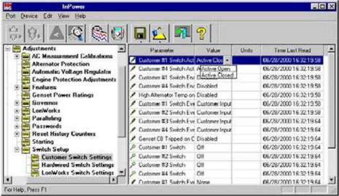
Switch Setup: Contains a group of miscellaneous switch parameters for monitoring and for setting switches to a specific state. An example of switch some states are: Enable or Disabled, Started or Stopped, On or Off, Active Open or Active Closed, etc., The settings depends on the type switch selected.
Many of these features contain sub menus of additional adjustment features. Use Device Explorer to expand each of these categories to view the sub-menu of adjustments.
How to Make Adjustment:
Located to the left of each parameter is an icon that indicates if the parameter can be adjusted or if it is for Monitoring
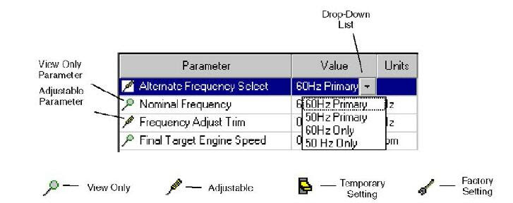
The screwdriver icon is used for trims and settings that can be written permanently to the device (read and write). When the cursor is placed over a parameter that can be adjusted, the range for the parameter is displayed .

The magnifying glass indicates that the parameter value is being monitored (read only). The switch icon is used to display settings that can be temporarily written to a device. The wrench icon represents factory settings that are not adjustable with InPower.
NOTICE
The value being monitored will not automatically update. The user can double click on the parameter to update the value field or click on the Refresh button, on the toolbar.
Each parameter displays the current value and the units of measure for that value. Review this information before making adjustments. Parameter value trims and settings are displayed. Trims are numeric values that are entered directly into the Value cell. Settings are selected from drop down lists, and they consist of several types of values such as On/Off and Enable/Disable.
To change a parameter value, double click inside the Value cell of the parameter that you wish to change.
The current value will be highlighted, if there are only a few choices, a drop-down arrow will be displayed next to the Value.
If an arrow is displayed, click on the arrow to view a drop-down list of the available settings. Click on the desired setting, and it will be entered into the Value cell.
If you do not see an arrow, begin typing the new value, the new value entry will overwrite the current value. If the value entered is above or below the range of acceptable values, an error message dialog box will be displayed.
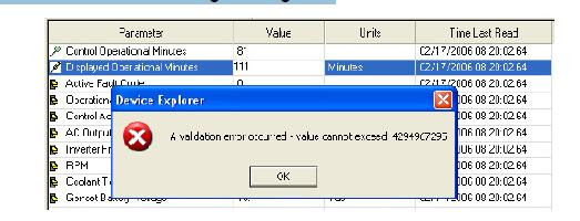
Review the information in the dialog box to see the value limits, before clicking OK, to close the error message dialog box.
Saving Adjustments
Edit Mode: When selected, a parameter value remains in the edit mode (to change a numeric value or select from a drop-down list). When finished making adjustments, press the enter key or click on another parameter value to exit the edit mode.
Saving Adjustments: Adjustments are written to the device as they are entered. To make these changes permanent, click on the Save Trims button, on the toolbar (floppy disc) or click on the Device menu and select Save Adjustments. Changes in adjustments will immediately alter the device's performance.
After the Save Adjustments button is selected, a Save Adjustments dialog is displayed. This feature allows you to view and confirm your changes by clicking on Save. You can make final edits within this dialog by double clicking inside the New Value box and entering a new parameter value or you can reset all of your changes by clicking on the Cancel button.
Saved adjustments are written to the Audit Trail in the Monitor feature. Refer to the Audit Trail to review the record of adjustment changes.
If the user loses connection with the device before saving an adjustment, the change will not be saved.
Adjustment Examples
The following examples are provided to demonstrate how typical trim and setting adjustments are made.
Some measurements and adjustments are done while the genset is running. Do not attach or remove test meters while the genset is running.
WARNING
Hazardous voltage can cause severe personal injury or death. Voltage and frequency measurements must be performed by trained and experienced personnel only. Do not attach or
remove test meters while the equipment is running. Refer to the equipment Operator's Manual for important safety precautions.
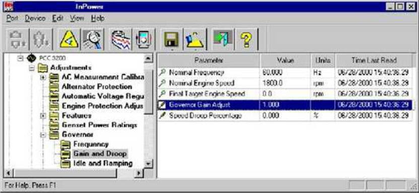
Example: In this example, InPower is used to adjust the governor gain (refer to the specific engine model T&R manual for additional governor adjustment details)
Select the Governor - Gain and Droop feature and then double click on the Gov. Gain Adjust Trim
Value cell.
Make a note of the existing Value reading. The range of adjustment is 0.05 to 10 (1 is the factory default setting).
Increase or decrease the value as needed to obtain the proper load response. If the gain is set too high, engine speed will hunt or oscillate, and if the gain is set too low, the engine will respond too slowly to changes in the load.
Click on the Save Trims button, on the toolbar, to write the new value to the device. Continue adjusting until satisfactory response time and stability are obtained.
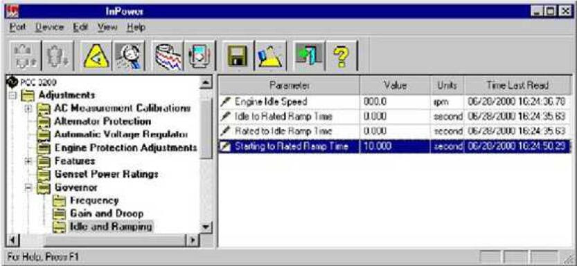
Example: In this example, InPower is used to increase the Starting to Rated Ramp Time. Select the Governor - Idle and Ramping feature, from the Adjustments directory. Double click on the Value cell for Starting to Rated Ramp Time. This adjustment sets the desired time interval between starting and rated power. The current setting will be highlighted. For this example, enter 10 (for 10 seconds) into the Value cell. (For faster startup and for NFPA 110 compliance, set this value to zero.) Click on the Save Trims button on the toolbar to write the new value to the device.
Example: In this example, InPower is used to adjust the automatic voltage regulator to obtain
the correct AVR gain setting.
With the genset OFF, attach a calibrated volt meter to the AC output leads from L1 to L2.
Start the genset and allow it to warm up. Apply and remove a load from the genset while observing the voltage meter reading.
Select the Automatic Voltage Regulator feature, and then double click on the AVR Gain Adjust
parameter Value cell.
Make a note of the existing Value reading. The range of adjustment is 0.05 to 10. Enter a higher or lower value as required. If the gain is set too high, output voltage will be unstable. If the gain is set too low, the output voltage will respond sluggishly to changes in load and overshoot may result.Click on the Save Trims button, on the toolbar, to write the new value to the device.
Example: In this example, InPower is used to make a setting change to one of the Switch Setup
parameters.
Select the Switch Setup feature in the Adjustments directory. Click on the Value cell for Customer
Switch Settings. Double click on the Value cell for Customer #1 Switch Active State Selection. The
current setting will be highlighted and a drop-down arrow will be displayed in the Value cell.
Click on the drop-down arrow to display the setting choices. The user can set the state to
either Active Open or Active Closed. To make the selection, click on the desired switch state.
Click on the Save Trims button, on the toolbar, to write the new value to the device.
Example: In this example InPower is used to adjust an XY table.
NOTICE
InPower will only allow adjustments to engine protection parameters that result in increased
engine protection. Select the Engine Protection Adjustments feature and double click on the Value cell for LCP Warning
Threshold. The current threshold settings are displayed in a graph. Pressure, in psi, is displayed on the Y-axis and engine speed is displayed on the X-axis.

Editing can be performed in the Graph Mode or in the Spreadsheet Mode).
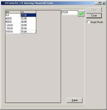
To change to the Spreadsheet Mode, click on the Graph Mode checkbox to remove the check mark.
Edit in the Graph Mode by dragging a threshold point on the graph to the desired setting. When the cursor is in the correct location, a pointing hand will appear on the graph. Select the hand by holding down on the mouse button, continue to hold down on the mouse button while dragging the point to the desired location.
Click on Save, to update the most recent changes. Click on Close when you are finished making changes.Click on the Save Trims button, on the toolbar, to write the new value to the device.
Edit in the Spreadsheet Mode by clicking on a value cell and entering the parameter value in the edit box,next to the check mark. Click on the check mark to enter the new value into the spreadsheet. Both the RPM and PSI values can be edited.
In this example, the user can change the LCP warning threshold at 1200 rpm to 20.5 psi. Use either the drag-and-drop method to move the point on the graph, or enter the new value into the spreadsheet.Click on Save to update the most recent changes. Click on Close, when you are finished making changes.
Click on the Save Trims button, on the toolbar, to write the new value to the device.
The Paste button is used to import spreadsheet value data from an Excel spreadsheet.
Service personnel will not need to use this feature because the data is already provided. Generally,only minor adjustments are required.
Cummins InPower Pro V12.5 with InCal Diagnostic software
Comments