 Articles
Carbon Dioxide (CO2) Capture, Storage & Control | Coal Gasification Encyclopedia
by Rudy P. SysAdmin at howtofindthemoneyINCREASING IMPORTANCE OF CARBON DIOXIDE EMISSIONS CONTROL
Carbon dioxide (CO2) capture, utilization, and sequestration (or storage) (CCUS) is increasingly becoming a core supporting technology component of clean coal projects, such as coal gasification facilities, to reduce the overall environmental impact of coal utilization.
Historically, the focus of emissions control was on sulfur dioxide and particulates, where a typical pulverized coal (PC) or coal gasification power plant was required to incorporate supporting technology to remove these pollutants to meet specific emissions regulations. Along with stricter limits on these as well as a broad range of pollutants including mercury, attention has also fallen on the issue of CO2 emissions from fossil fuel-based power production, given that 85% of greenhouse gas emissions are energy related, and 95% of those gas emissions are CO2. CO2 is becoming the focus of attention as its relation to global climate change becomes clearer.
Rule-making or regulatory control being put in place for controlling CO2 is likely to keep changing and evolving over time. Future possibilities range from economic incentives to reduce CO2 emissions, to firm government regulations that could severely limit or impose cap and trade scenarios on emissions of CO2, any of which would require an adjustment throughout the energy industry and beyond. Gasification research and development is focused on solutions to the problem of CO2 release that will not negatively impact energy use or economic growth. Regulations or other effects of carbon cap scenarios are likely to serve as drivers for gasification because of its inherent advantages for CO2 capture, given that its overall process scheme can be easily designed (or modified) to allow for economic CO2 capture.
Gasification vs. Combustion in CO2 Emissions
In a conventional pulverized coal combustion-based power plant, air and fuel are mixed, combusted and then exhausted at near atmospheric pressure. Since air contains a large amount of nitrogen which substantially dilutes the combustion exhaust gases, CO2 is considerably diluted in the exhaust, and being near ambient pressure, the exhaust gases are of low density. Removing the CO2 following combustion is known as "post-combustion" CO2 capture, which is made relatively difficult, energy-intensive, and expensive because of the dilution and low pressure of the exhaust gases.
In gasification, on the other hand, oxygen is normally supplied to the gasifiers and just enough fuel is combusted to provide the heat to gasify the rest; moreover, gasification is often performed at elevated pressure. The resulting syngas is typically at higher pressure and not diluted by nitrogen, allowing for much easier, efficient, and less costly removal of CO2 (and other pollutants as well, demonstrated by the extremely low emissions of sulfur and nitrous oxides in addition to low levels of particulate matter and other contaminants such as heavy metals characteristic of gasification processes). Gasification and integrated gasification combined cycle (IGCC)'s unique ability to easily remove CO2 from the syngas prior to its combustion in a gas turbine (called "Pre-Combustion" CO2 capture) is one of its great advantages over conventional combustion.
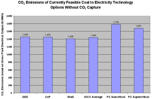
The following figure demonstrates that even without taking into account the advantages IGCC has in ease of carbon capture it still emits less carbon dioxide emissions than the coal-fired PC plants.
This figure demonstrates that even without taking into account the advantages IGCC has in ease of carbon capture it still emits less carbon dioxide emissions than the coal-fired PC plants.
If capturing and storing CO2 is incentivized or mandated, then the benefits of IGCC over PC plants become even more pronounced. The ease and effectiveness with which carbon capture technology is added to IGCC systems is shown in the following graph. The economic advantages that PC has over IGCC without carbon capture are made up for and even reversed slightly, with IGCC being slightly less expensive on a mills/kWh basis. In addition, the capture technology used with IGCC is able to remove approximately 90 percent of CO2, giving it a slight edge against both subcritical and supercritical coal-fired PC power plants.
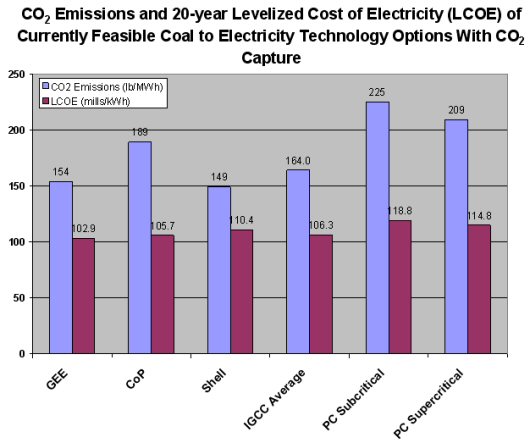
The ease and effectiveness with which carbon capture technology is added to IGCC systems is shown in this graph.
CARBON DIOXIDE CAPTURE APPROACHES
Carbon dioxide (CO2) capture systems may be classified into three categories: post-combustion, pre-combustion, and oxy-combustion. The following figure illustrates those capture approaches, noting challenges, as well as established and developmental technologies in those areas.
This figure illustrates those capture approaches, noting challenges, as well as established and developmental technologies in those areas.
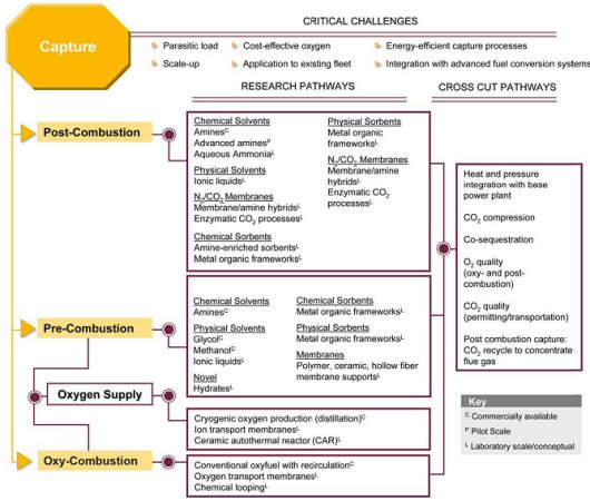
More detailed discussion on the post-combustion, pre-combustion, and oxy-combustion technologies for CO2 capture follows.
Post-Combustion CO2 Capture
Post-combustion CO2 capture is primarily applicable to conventional natural gas and pulverized coal-fired (PC) power generation. In a typical PC power plant, fuel is burned with air in a boiler to produce steam, which drives a turbine to generate electricity. The boiler exhaust, or flue gas, consists mostly of nitrogen (N2), and CO2. Separating CO2 from this flue gas stream is challenging for several reasons:
- CO2 is present at dilute concentration (typically 13 to 15 volume percent for PC power plants and 3 to 4 percent for natural gas-fired plants) and at low pressure (slightly above atmospheric); thus, a large volume of gas has to be treated.
- Trace impurities (e.g., particulate matter, sulfur dioxide [SO2], nitrogen oxides [NO2] in the flue gas can degrade sorbents and reduce the effectiveness of certain CO2 capture processes.
- CO2 is captured at low pressure. Compressing it from atmospheric to pipeline pressure (about 2,000 psia) will incur a large auxiliary power load on the overall power plant system.
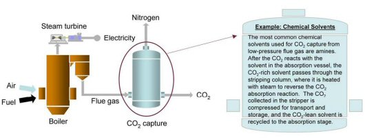
A post-combustion CO2 capture absorption process based on chemical solvents such as amines is pictorially shown below. These types of processes have been developed and deployed commercially in the refinery and chemical industries. To date, however, their use in PC power plants has been restricted to slipstream applications, and no definitive analysis exists as to the actual costs for a full-scale capture plant. Preliminary analysis conducted at NETL indicates that CO2 capture via amine scrubbing and compression to 2,200 psia could raise the cost of electricity from a new supercritical PC power plant by 65 percent, from 5.0 cents/kilowatt-hour (kWh) to 8.25 cents/kWh.
Preliminary analysis conducted at NETL indicates that CO2 capture via amine scrubbing and compression to 2,200 psia could raise the cost of electricity from a new supercritical PC power plant by 65 percent, from 5.0 cents/kilowatt-hour (kWh) to 8.25 cents/kWh.
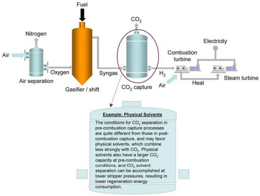
Pre-Combustion CO2 Capture for Gasification Application
Pre-combustion CO2 capture related to a gasification plant is pictorially depicted below. In gasification reactions, the amount of air or oxygen (O2) available inside the gasifier is carefully controlled so that only a portion of the fuel burns completely. This “partial oxidation” process provides the heat necessary to chemically decompose the fuel and produce synthesis gas (syngas), which is composed of hydrogen (H2), carbon monoxide (CO) and minor amounts of other gaseous constituents. The syngas is then processed in a water-gas-shift (WGS) reactor, which converts the CO to CO2 and increases the CO2 and H2 mole concentrations to about 40 percent and 55 percent, respectively, in the syngas stream.
At this point, the CO2 has a high partial pressure, which significantly improves the driving force for various types of separation and capture technologies. After CO2 removal, the H2 rich syngas can be converted to power. One application is to use H2 as a fuel in a combustion turbine to generate electricity, in the context of a combined cycle plant, where additional electricity is generated by extracting the energy from the combustion turbine flue gas via a heat recovery steam generator (HRSG). Another application, currently being developed under the NETL Fuel Cell Program, is to utilize the H2 for power generation using fuel cells, with the intent of significantly raising overall plant efficiency. Because the gasification process is operated at high pressure and CO2 is present at much higher concentrations in the syngas (i.e., in comparison with post-combustion flue gas), pre-combustion CO2capture has the potential of being less expensive than post-combustion CO2 capture. For the same amount of CO2 captured, a much smaller volume of gas needs to be treated, leading to much smaller equipment size and lower capital costs.
For the same amount of CO2 captured, a much smaller volume of gas needs to be treated, leading to much smaller equipment size and lower capital costs.
NETL has identified various research pathways for pre-combustion CO2 capture. Near-term applications of CO2 capture from pre-combustion systems will likely involve physical or chemical absorption processes, with the current state-of-the-art being a physical glycol-based solvent called Selexol. Mid-term to long-term opportunities to reduce capture costs through improved performance could come from membranes and sorbents currently at the laboratory stage of development. Preliminary analysis conducted at NETL shows that CO2 capture and compression using Selexol raises the cost of electricity from a newly built IGCC power plant by about 30 percent, from an average of 7.8 cents/kWh to 10.2 cents/kWh.1 Research being conducted by the NETL Gasification Systems Research Program is expected to improve gasification technology such that costs without capture are comparable to costs from pulverized coal without capture.
Oxy-Combustion CO2 Capture
The objective of pulverized coal oxygen-fired combustion is to combust coal in an enriched oxygen environment using pure oxygen diluted with recycled CO2 or water (H2O). The process is pictorially shown below. Under these conditions, the primary products of combustion are CO2 and H2O, and the CO2 can be captured by condensing the water in the exhaust stream. Oxy-combustion offers several additional benefits, as determined through large-scale laboratory testing and systems analysis:
- A 60-70 percent reduction in NOx emissions compared to air-fired combustion, mainly due to flue gas recycle, but also from reduced thermal NOx levels due to lower available nitrogen. Some nitrogen is still introduced into the system as nitrogen inherent to the coal matrix, and through air infiltration.
- Increased mercury removal. Boiler tests of oxy-fuel combustion using Powder River Basin (PRB) coal resulted in increased oxidation of mercury, facilitating downstream mercury removal in the electrostatic precipitator and flue gas desulfurization systems.
- Applicability to new and existing coal-fired power plants. The key process principles involved in oxy-combustion have been demonstrated commercially (including air separation and flue gas recycle).
Both pre-combustion and oxy-combustion utilize air separation to combust coal in an enriched oxygen environment. However, it is important to note that the amount of oxygen required in oxy-combustion is significantly greater than in pre-combustion applications, increasing CO2 capture costs. A higher purity oxygen stream would also need to be used. Oxygen is typically produced using low-temperature (cryogenic) air separation, but novel oxygen separation techniques such as ion transport membranes and chemical looping systems are being developed to reduce costs.
CARBON DIOXIDE CAPTURE TECHNOLOGY OPTIONS
All gasification-based conversion processes require removal of hydrogen sulfide (H2S; an acid gas) from the synthesis gas (syngas) as part of the overall plant configuration. Typical acid gas removal (AGR) processes employed for gasification design are either a chemical solvent system (e.g., methyl diethanolamine [MDEA]) or a physical solvent system (e.g., Rectisol or Selexol). Process selection is mostly dependent on the syngas cleanup requirement and costs. Conventional chemical/physical AGR processes using MDEA, Rectisol or Selexol are commercially proven technologies and can be designed for selective removal of carbon dioxide (CO2) (also an acid gas), in addition to H2S, from a syngas stream. For significant capture of CO2 from a gasification plant (e.g., > 80%) the carbon monoxide (CO) in the syngas must first be converted to CO2 and hydrogen (H2) via a water-gas-shift (WGS) process upstream of the AGR plant.
It should be noted that in addition to the well-used chemical/physical processes such as MEA, Selexol and Rectisol for CO2 removal from process gas streams, a whole range of other technologies are at varying levels of implementation, investigation and development, as shown in the following chart.
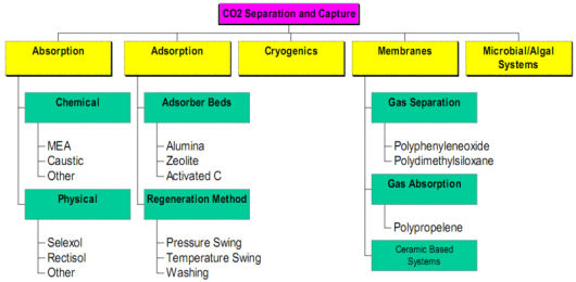
It should be noted that in addition to the well-used chemical/physical processes such as MEA, Selexol and Rectisol for CO2 removal from process gas streams, a whole range of other technologies are at varying levels of implementation, investigation and development.
For gasification applications, or integrated gasification combined cycle (IGCC), the plant modifications required to add the ability to capture CO2 are minimal. The syngas produced by the gasifiers needs to be treated through various processes for the removal of impurities already in the gas stream, so all that is required to remove CO2 is to add the necessary equipment, an absorber and regenerator, to this process train. In combustion applications, modifications must be done to the exhaust stack and because of the lower concentrations of CO2 present in the exhaust, much larger volumes of total gas require processing, necessitating larger and more expensive equipment.
COST AND COMPLEXITY OF CARBON DIOXIDE CAPTURE OPTIONS FOR POWER PLANTS
Performance and Cost Comparison
NETL has completed a comprehensive study comparing the performance and cost of various fossil fuel-based power generation technologies, with and without carbon dioxide (CO2) capture. Power generation systems investigated include integrated gasification combined cycle (IGCC), pulverized coal (PC), and natural gas combined cycle (NGCC) plants. Performance and cost evaluations were made based on a consistent technical and economic approach that reflects current market conditions for plants starting operation in 2010. Twelve different power plant configurations were analyzed and they are as follows: 1
- IGCC - based on GE Energy's gasification technology operating at the 'radiant cooling mode of operation' – without CO2 capture
- IGCC - based on GE Energy's gasification technology operating at the 'radiant cooling mode of operation' – with CO2 capture
- IGCC - based on ConocoPhillips' gasification technology – without CO2 capture
- IGCC - based on ConocoPhillips' gasification technology – with CO2 capture
- IGCC - based on Shell's gasification technology – without CO2 capture
- IGCC - based on Shell's gasification technology – with CO2 capture
- Subcritical PC power plant without CO2 capture
- Subcritical PC power plant with CO2 capture
- Supercritical PC power plant without CO2 capture
- Supercritical PC power plant with CO2 capture
- NGCC power plant without CO2 capture
- NGCC power plant with CO2 capture
Among these systems, IGCC CO2 capture is pre-combustion based, using selective Selexol technology. PC and NGCC power plant CO2 capture designs are post-combustion, using amine absorption.
Performance
Figure 1 shows the estimated thermal efficiency of the various power generation systems studied, in terms of high heating value (HHV). As shown, CO2 capture incurs a sizable thermal efficiency penalty. Comparing just the coal-based power generation plants, potential efficiency reduction for the pre-combustion IGCC plants ranges from 6.4 to 10.9 absolute percent (with an average of 8.7%), whereas an 11% reduction was estimated for post-combustion flue gas CO2 capture for the PC plants.
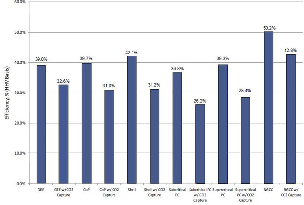
Figure 1 – Net Plant Efficiency (HHV Basis)
These performance results showing more favorable efficiency of IGCC vs. PC types are to be expected, considering that the CO2 in IGCC syngas is much more concentrated and pressurized than the CO2 in the flue gas of a PC power plant. Both concentration and pressure aid in separating CO2 from the syngas. The high CO2 partial pressure allows for the use of physical separation processes, whereas the PC gas separation must use a chemical absorption process because of low CO2 partial pressure. Chemical absorption and regeneration is relatively more energy intensive.
Cost (Total Plant Cost and Levelized Cost of Electricity)
Figure 2, below, shows the estimated Total Overnight Cost (TOC) of the various power generation systems, with and without CO2 capture. The TOC for each plant was calculated by adding owner's costs to the Total Plant Cost (TPC). The TPC for each technology was determined through a combination of vendor quotes, scaled estimates from previous design/build projects, or a combination of the two. TPC includes all equipment (complete with initial chemical and catalyst loadings), materials, labor (direct and indirect), engineering and construction management, and contingencies (process and project). Escalation and interest on debt during the capital expenditure period were estimated and added to the TOC to provide the Total As-Spent Cost (TASC). As shown, the average TOC for IGCC CO2 capture cases is $3,568/kW, whereas the average TOC of post-combustion flue gas CO2 capture for the PC plants is $3,590/kW.
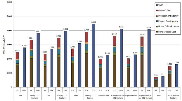
Figure 2 – Plant Capital Costs
The cost of electricity (COE) is the revenue received by the generator per net megawatt-hour during the power plant's first year of operation, assuming that the COE escalates thereafter at a nominal annual rate equal to the general inflation rate, i.e., that it remains constant in real terms over the operational period of the power plant. The COE results are shown in Figure 3 with the capital cost, fixed operating cost, variable operating cost, and fuel cost shown separately. In the capture cases, the CO2 transport, storage, and monitoring (TS&M) costs are also shown as a separate bar segment. In non-capture cases, NGCC plants have the lowest COE (58.9 mills/kWh), followed by PC (average 59.2 mills/kWh) and IGCC (average 77.2 mills/kWh). In capture cases, NGCC plants have the lowest COE (85.9 mills/kWh), followed by PC (average 108.2 mills/kWh) and IGCC (average 111.8 mills/kWh).
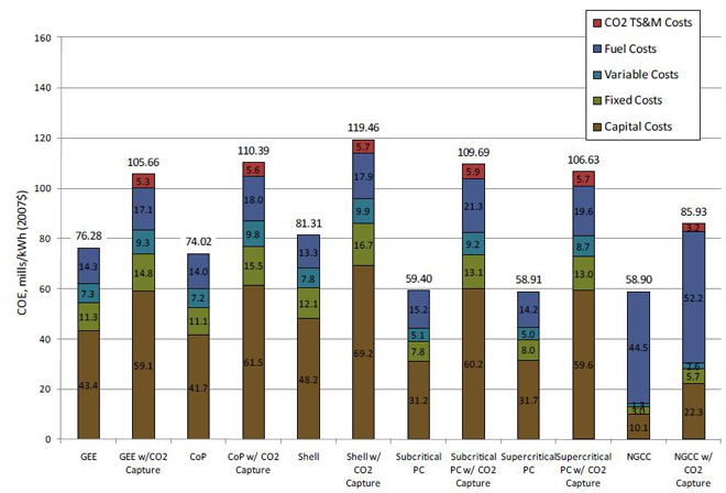
Figure 3 – Cost of Electricity by Component
SPECIFIC IMPACTS ON IGCC PLANT DESIGNS FROM CARBON DIOXIDE CAPTURE
In foregoing discussion, results of NETL's comprehensive study comparing the performance and cost of various fossil fuel-based power generation technologies with and without carbon dioxide (CO2) capture were reviewed. Of particular interest in that study was the companion set of integrated gasification combined cycle (IGCC) designs, using GE's gasification technology, which can be used to illustrate the design changes needed for CO2 capture.
Current Technology - IGCC Plant Design
Figure 1 shows a simplified block flow diagram (BFD) of a market-ready IGCC design without CO2 capture. As shown, the IGCC plant consists of the following processing islands, of which a more detailed description of each can be found in the cited NETL referenced report: 1
- Gasification - GE Energy (GEE) based technology, operating in radiant cooling mode, with high temperature syngas heat recovery.
- Air Separation Unit (ASU) - Integrated into the power train extracting 16% of its air from the gas turbine compressor and producing a high-pressure nitrogen (N2) stream for turbine combustor NOx control.
- Quench and Syngas Scrubbing - For additional syngas cooling and the removal of entrained fine particulates as well as water soluble contaminates (e.g., ammonia and chlorides) from the syngas.
- COS (carbonyl sulfide) Hydrolysis - Converts the carbonyl sulfide (COS) in the syngas to H2S before sulfur is removed downstream by the acid gas removal (AGR) unit.
- Gas Cooling, Boiler Feed Water (BFW) Heating, and Knockout - Cools the syngas leaving COS hydrolysis, before it is fed to Hg removal and the AGR unit, by heat exchanging with the boiler feed water. The produced water condensate is sent to the sour water stripping plant.
- Sour Water Stripper - Takes the produced water/condensate from the low-temperature cooling processes, including that from the scrubber, and strips off the gas contaminants such as H2S, ammonia (NH3) and CO2 etc., before the water can be sent onto the plant waste water treatment facility.
- Mercury Removal - via activated carbon bed.
- Selexol - A conventional Selexol unit is used for H2S removal.
- Claus Plant & Hydrogenation Reactor and Gas Cooler - A conventional Claus process to recover sulfur from H2S as a salable solid sulfur product, followed by hydrogenating the Claus tail gas and recycling it back to the Selexol unit.
- Syngas High Pressure Reheat/Syngas Expander - Heat removal and expansion of the high pressure, clean syngas to recover additional energy before sending it onto the power train.
- Combined-Cycle Power Train - GE's advanced F Class gas turbine, which includes a heat recovery steam generator (HRSG) and a steam turbine.

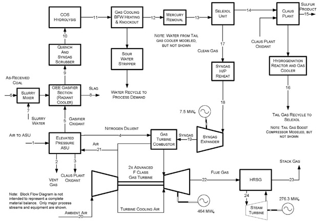
Figure 1 – IGCC without CO2 Capture Block Flow Diagram
IGCC Design Change to Enable CO2 Capture
Figure 2 shows a companion simplified block flow diagram (BFD) of a market-ready IGCC design with CO2capture. The design is for 90% CO2 capture from the IGCC plant. As shown, in comparison with the no-capture design, there are two key process plant modifications needed:
- Shift Reactors - A water-gas-shift (WGS) reactor is added to replace the COS Hydrolysis plant. This was done to convert all carbon monoxide (CO) in the syngas to CO2 and H2, so that the CO2 can be removed downstream in the AGR plant. Since the WGS catalyst also serves to hydrolyze COS, a separate COS plant is no longer needed.
- Modify the conventional Selexol plant to enable selective removal of both H2S and CO2. In principle, this involves adding an additional absorber column and flash drums onto the plant, of which the technology vendor, UOP, would help with the detailed design, once the syngas flow and composition, and the CO2 product specifications, are clearly defined.
Figure 3 shows a simplified BFD for a selective Selexol design for both H2S (acid gas to the Claus plant) and CO2 removal.
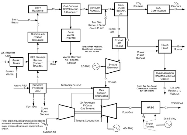
Figure 2 – BFD of an IGCC Plant Configuration with CO2 Capture
An additional processing step of CO2 dehydration and compression (shown in Figure 2 as CO2 Compression) is added to bring the produced CO2 to pipeline transport pressure and purity specifications.
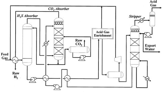
Figure 3 – BFD of a Selective Selexol Design for H2S and CO2 Removal
The 10 largest coal producers and exporters in Indonesia:
Sponsor Ads
Created on Jul 18th 2019 01:44. Viewed 704 times.

Comments
No comment, be the first to comment.
